
EXAMINATION OF JAPANESE AIRCRAFT AILERON TIP
USS ENTERPRISE (CV-6), 11 APRIL 1945
(Richard Lane)
FOREWORD
In 2004, I purchased a Japanese aircraft aileron tip on eBay. The
item was reported to be the tip of stabilizer from a Kamikaze plane that
hit the USS Enterprise on 11 Apr 45. The auction’s description
stated that the seller’s uncle was a sheet metal worker at that
time on the USS Enterprise.
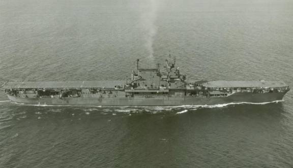
Figure 1: USS Enterprise’s starboard beam on September
13, 1945. Original Puget Sound Photo: R. Lane collection.
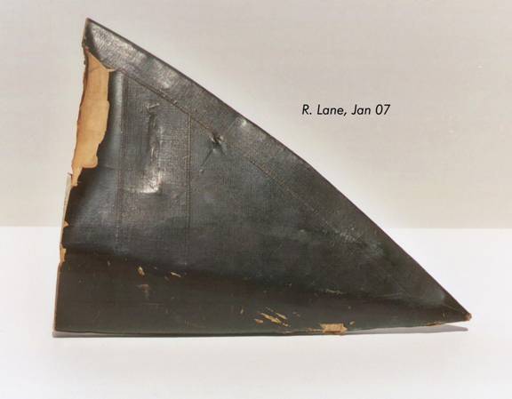
Figure 2: Aileron tip upper surface.
INITIAL ANALYSIS
The lower surface of the aileron tip’s fabric has penciled text: “April 11, 1945, Port Side FR.157, USS Enterprise.” The “Port Side” refers to side of the USS Enterprise that was attacked by the Kamikaze plane. The “FR 157” may refer to a frame section on the USS Enterprise that was damaged by a Kamikaze on 11 Apr 45.
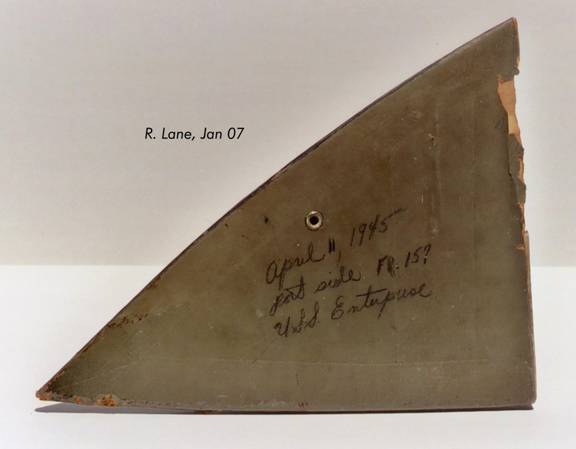
Figure 3: Aileron tip lower surface.
DETAILED ANALYSIS – KAMIKAZE ATTACK ON USS ENTERPRISE
Before analyzing the aileron tip, this article will summarize the 11 Apr 45 Kamikaze attacks on the USS Enterprise. A full copy of the USS Enterprise Damage Report is available at cv6.org. Excerpts from the report are included below.
On 24 March 1945, Enterprise anchored in Ulithi where repairs to the damage received on 18 and 20 March were undertaken by the ship's force and personnel from USS Jason. They were not completed in time for her to participate in the 1 April landings on Okinawa, but by 7 April she was able to join Task Group 58.3 operating to the east of Okinawa. A large-scale Kamikaze attack developed against Task Group 58.3 on 11 April northeast of Okinawa. At 1345 two large groups of Japanese aircraft were noted closing from the north. Enterprise opened fire on two planes at 1408, shooting one down about 1500 yards off the starboard quarter. The other dived on the port quarter, struck two 40mm mounts and fell into the sea. The bomb carried by the plane detonated beneath the ship. At 1500 another Japanese plane carrying a bomb attempted a suicide dive but missed and struck the water 45 to 50 feet off the starboard bow.

Figure 4: USS Enterprise’s flight deck showered with sea
water and flaming
debris from the first Kamikaze near-miss aircraft. Photo
courtesy cv6.org.

Figure 5: Approximate path of the first Kamikaze plane and near
miss of 11 Apr 45.
Scanned from an original
copy of the USS Enterprise (CV6) War History,
7 Dec 1941 to 15
Aug 1945 (dated 30 Apr 1947). Diagram
courtesy Joe Nichols.
The outboard gun shields and semicircular platforms of 40mm mounts Nos. 8 and 10 were sheared off or bent by impact of the plane and blast from the first near-miss. Parts of the plane remained in the gun tubs.
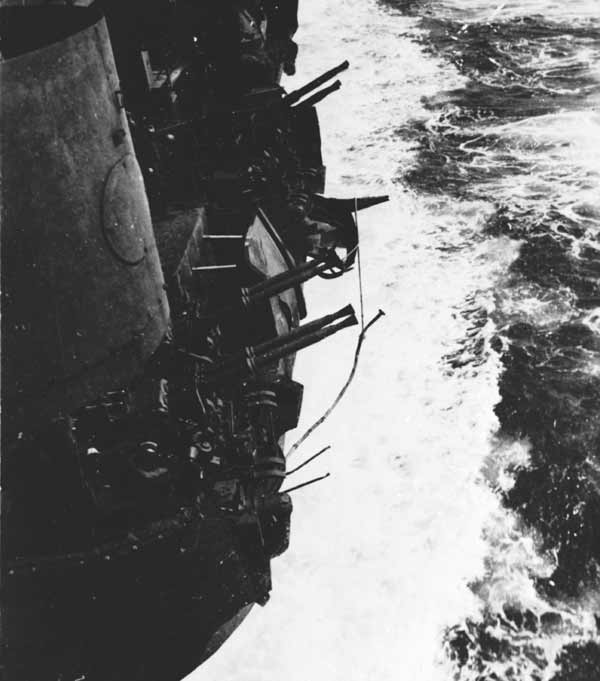
Figure 6: First near-miss Kamikaze plane sheared off the outboard
shields of the two 40mm anti-aircraft
gun platforms on Enterprise's
port quarter, 11 Apr 45. Photo courtesy cv6.org.
The action report stated the belief that both near-misses were by Judy-11's. However, a photograph shows a head-on view just before the crash, which indicates that the plane which grazed the port quarter was a Zeke-52, with a bomb slung under its fuselage. The plane which fell off the starboard bow was probably a Judy-11, judging from the action report and from a photograph of the piece of the wing recovered on the flight deck.
The first plane's engine struck the blister at frame 136, tearing a 3-foot by 2-foot hole into D-54-F at the waterline. Except where torn open by the impact of the plane's engine, the welded blister plating did not develop cracks or tears from the first near-miss. In contrast to this, rivets popped and seams opened in the original hull even where protected by the blister.

Figure 7: Damage to Enterprise's hull, port-side aft, caused by
the first Kamikaze near-miss,
11 Apr 45. Photo courtesy cv6.org.

Figure 8: Approximate path of the first Kamikaze plane and near
miss of 11 Apr 45.
Scanned from an original copy of the USS Enterprise
(CV-6) War History,
7 Dec 1941 to 15 Aug
1945 (dated 30 Apr 1947). Diagram
courtesy Joe Nichols.
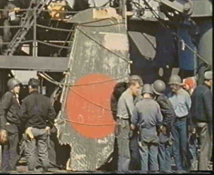
The bomb from the second Japanese plane detonated 45 to 50 feet off the starboard bow, causing additional shock damage and slight structural damage in six tanks and voids. Water spray carried as far aft as the pilothouse and part of the plane wing was hurled to the flight deck. Note: Steve Ewing recounts how this wing piece was recovered in his book, “USS Enterprise (CV-6) The Most Decorated Ship of World War II” (1982), page 146. The passage reads; “A crewmember ran forward, took hold of the wing and began pulling it toward the island. Half way to his destination he stopped, pulled out a pen and wrote on the wing, “this wing is the property of W.W. Wahl AMM 1/C.”

Figure 9: John Yocum SC 3/c standing beside the wing of a "Judy" that
crashed into Enterprise CV-6, 11 Apr 45.
This wing is from the second
near-miss Kamikaze plane that attacked the Enterprise on 11
Apr 45.
The wing was preserved and placed on display in the Washington Navy
Yard after the war.
Photo courtesy cv6.org. Note: A color photo
of this same wing piece can be seen at Claus Kruger’s
J-aircraft.com
photo gallery at: http://www.j-aircraft.com/familyphotos/claus_kruger/flache_01l.jpg
Damage Report Conclusion: It is evident that the first near-miss Kamikaze plane was a Zeke-52 (A6M5) and parts of the plane remained in the gun tubs. The second Kamikaze plane was a Judy-11 and part of the plane’s wing was hurled onto the flight deck.
DETAILED ANALYSIS – AILERON TIP
The aileron tip measures 9 x 12 inches and is fabric covered on the lower and upper surfaces. The piece is in an amazing state of preservation and it appears as if this relic was stored away in a dark place for over 60 years. The fabric is still tight under tension and the paint is in excellent, original condition.
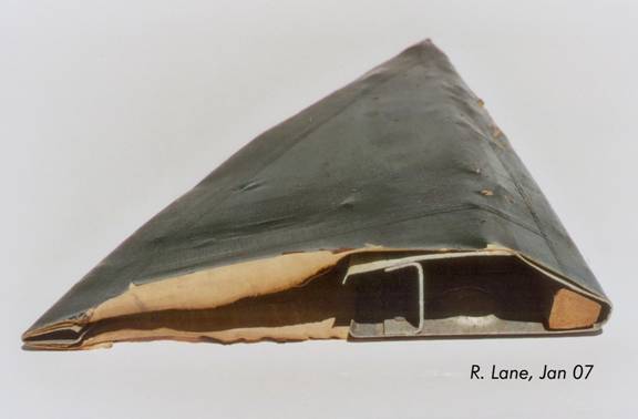
Figure 10: Aileron tip upper surface.
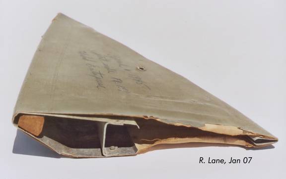
Figure 11: Aileron tip lower surface with penciled text.
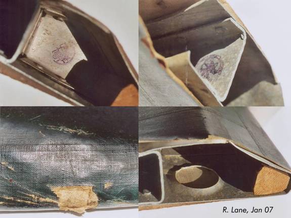
Figure 12: Detail of two internal ink stamps, close up of upper
fabric impact damage, and lightening hole/wood support piece.

Figure 13: Detail of another internal ink stamp and several fabric
threads/grommets.
The first step was to verify the type of aircraft this piece was removed from. From the official damage report, we know that one near-miss Kamikaze aircraft was a Zeke-52 and the other a Judy-11. Jim Long provided the following detailed analysis.
JIM LONG’S DETAILED ANALYSIS
I believe we can conclude that the aileron tip is from an A6M5 and not from a Judy type aircraft.
Using measurements and photo scans, I have located the tip piece on a copy of a portion of an official WWII technical diagram from a handling manual. See Figure 1.
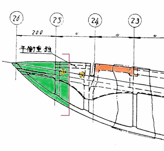
Figure 1. Close-up detail of the left wing tip of an A6M5
aircraft.
This diagram is from Page 381 of “Zero Fighter
Secret Documents,”
published by KK Bestsellers, Tokyo,
2001, ISBN4-584-17084-3 C0020.
The portion colored green represents
the piece referenced in this report...
Though this was a technical drawing from WWII and should have been accurate, it has a mistake on it. While doing this research, I discovered that the original draftsman misidentified the location of the aileron’s counterbalance weight at the outboard position. The four Japanese written characters in the space between Stations 25 and 26 mean “Balance Weight.” But the line points out a dashed-line item in the outer end between Stations 24 and 25 that I believe represents the piece of wood used in the nose of the aileron for added strength. The table that details the values and locations of the balance weights, appearing on the same page as the drawing, supports the supposition that the draftsman erred. The draftsman should have had his line running to the orange colored item, which was the outer counterbalance weight.
Rich reported that the piece of wood in his relic ran the whole length of the aileron tip. The drawing does not confirm that. Instead it indicates that the piece of wood ran only from the left side of the hinge cutout to the left side of the last rib in the aileron. The drawing is a Mitsubishi product and this might be significant. If we could determine that the Mitsubishi-built aileron was different from the Nakajima-built one in this respect, we would have some valuable information.
And now I call your attention to the two round items that I have color-coded in yellow. Rich said his piece had a small vent hole on the underside that had a metal grommet for reinforcement. We can see it in Figure 3, below. At first I thought these two yellow items on the drawing represented two such vent holes. But on closer examination, I noted that the holes were in areas that were made of metal. I looked around for an explanation and soon found something on one of Rich’s scans. A flanged lightening hole can just be seen in the shadow on one of the scans. I believe the circles on the drawing represent lightening holes, of which the outermost one is in Rich’s relic. The picture is in Figure 2, below.
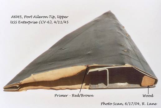
Figure 2: A lightening hole in the bottom surface of the metal
portion of the aileron tip.
The Douglas report doesn’t help us any with a detailed description of the construction of the aileron. Be that as it may, the portion that should interest us in this discussion is the information about the fabric material on control surfaces. The portion inspected was from the rudder, but I feel that it would be representative of the covering on the ailerons, as well. I’ve excerpted the material and am presenting it here Attachment 1. To complete this report, I’m including a scan of the complete aileron as Attachment 2, on which I’m showing the details I’ve spoken of, with the counterbalance weights shown in yellow, the wooden reinforcements shown in green, and the lightening holes shown in orange.
The little grommet hole is probably to equalize air pressure. It’s
just my guess. As for the colors, they seem about right. As
to whether they are Mitsubishi or Nakajima colors, I couldn’t say,
and I defer to Jim Lansdale on this question.
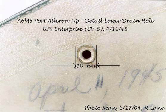
Figure 3: Small reinforced vent hole in the fabric on the bottom
surface of the aileron tip.
I conclude that Rich has a notable relic because we know that it came from a Zeke, and it is associated with a particular historical event.
ATTACHMENT 1
Excerpt from Report No. ES6744, ENGINEERING INSPECTION - JAPANESE ZEKE 52 AIRPLANE, February 1, 1945, by R. Anderson of the Douglas Aircraft Company, Inc., El Segundo Plant.
15.0 MISCELLANEOUS INVESTIGATIONS 15.1 FABRIC COVERING OF CONTROL SURFACES 15.11 GENERAL For the purpose of
determining the type and quality The fabric taken from
the specimen was found to be 15.12 MATERIALS 15.121 FABRIC MATERIALS The Japanese fabric covering material
rep- Examination
of two test specimens deter- The
weight of the fabric was determined to be 3.77 Reinforcing
and cover tapes are made from 15.122 COATING MATERIALS An
analysis of the surface coating mate- The flexibility
of the surface coating is 15.13 METHOD OP ATTACHING FABRIC The cover fabric was
found to be attached to the The cover fabric is
closed on the leading edge of It is considered
that the method of attaching fab-
15.14 METHOD OF APPLYING SURFACE COATING Examination of the coating
film by scraping through (a) Two brushed coats of clear
dope, cover Based
on the amount of clear dope remaining in the Adhesion
of the coating and cover tapes to the base |
______________________________________________________________________
ATTACHMENT 2.

COLOR ANALYSIS
Jim Lansdale analyzed the aileron tip and obtained color readings of Munsell 2.5 GY2/2 for upper surface dark green and the lower surface Munsell 7.5 Y 4/2 (close to Federal Standards 595 FS-16350). Jim concluded that these colors match a Nakajima produced A6M5 Zero Fighter (Zeke 52).
CONCLUSIONS
From the USS Enterprise 11 Apr 45 damage report, we know the first Kamikaze plane was an A6M5 Zero and parts of the plane remained in the 40mm gun tubs. The second Kamikaze plane was a Judy-11 and part of the plane’s wing was hurled to the flight deck. From Jim Long’s detailed analysis, we know this aileron tip was from the port side of an A6M5 Zero. Jim Lansdale further documented that the upper/lower colors matched a Nakajima produced A6M5. What is still unknown, and requires further research, is information about the Japanese pilots of either the Judy-11 or Zeke-52 from these 11 Apr 45 Kamikaze missions.
REFERENCES
1. USS Enterprise (CV6) War History, 7 Dec 1941 to 15 Aug 1945 (dated
30 Apr 1947).
Joe Nichols purchased an original copy of this document on eBay in 2004. He
provided me the detailed scans of the diagrams that depict the Kamikaze
attacks on 11 Apr 45.
2. cv6.org. The image library has several photographs of the damage
caused by the A6M5 Zero Fighter and Judy-11 that attacked the USS Enterprise
on 11 Apr 45. The web site also has the damage report for the USS
Enterprise.
3. Jim Lansdale and Jim Long. Both were instrumental in documenting
this aileron tip. Jim Long provided a detailed report that was
incorporated in this article.
4. USS Enterprise (CV-6) The Most Decorated Ship of World War II,
Steve Ewing, Pictorial Histories Publishing Company, 1982